CVD Silicon–Carbon Anode Preparation Process and FBCVD Reactor Selection Key Points
CVD silicon–carbon anode preparation is one of the core routes for next-generation lithium-ion battery anode materials, and the FBCVD (fluidized-bed chemical vapor deposition) reactor is the key equipment that determines production capacity, cost, and consistency. This article outlines the complete CVD silicon–carbon anode preparation process and provides a checklist of critical parameters to evaluate when selecting an FBCVD reactor.
I. Overview of the CVD Silicon–Carbon Anode Preparation Process
Mainstream CVD silicon–carbon anode preparation is divided into three major stages: silicon source deposition, carbon coating, and post-treatment. The overall process is as follows:
- Precursor preparation: Porous carbon (resin carbon, biomass carbon, or graphite-based porous carbon) is crushed, screened, and dried to control particle size distribution and moisture content, serving as the skeleton for silicon deposition.
- Silicon source vaporization: Silane (SiH₄) or chlorosilane-type silicon sources are metered and diluted (usually with nitrogen or argon as carrier gas) before entering the reaction zone.
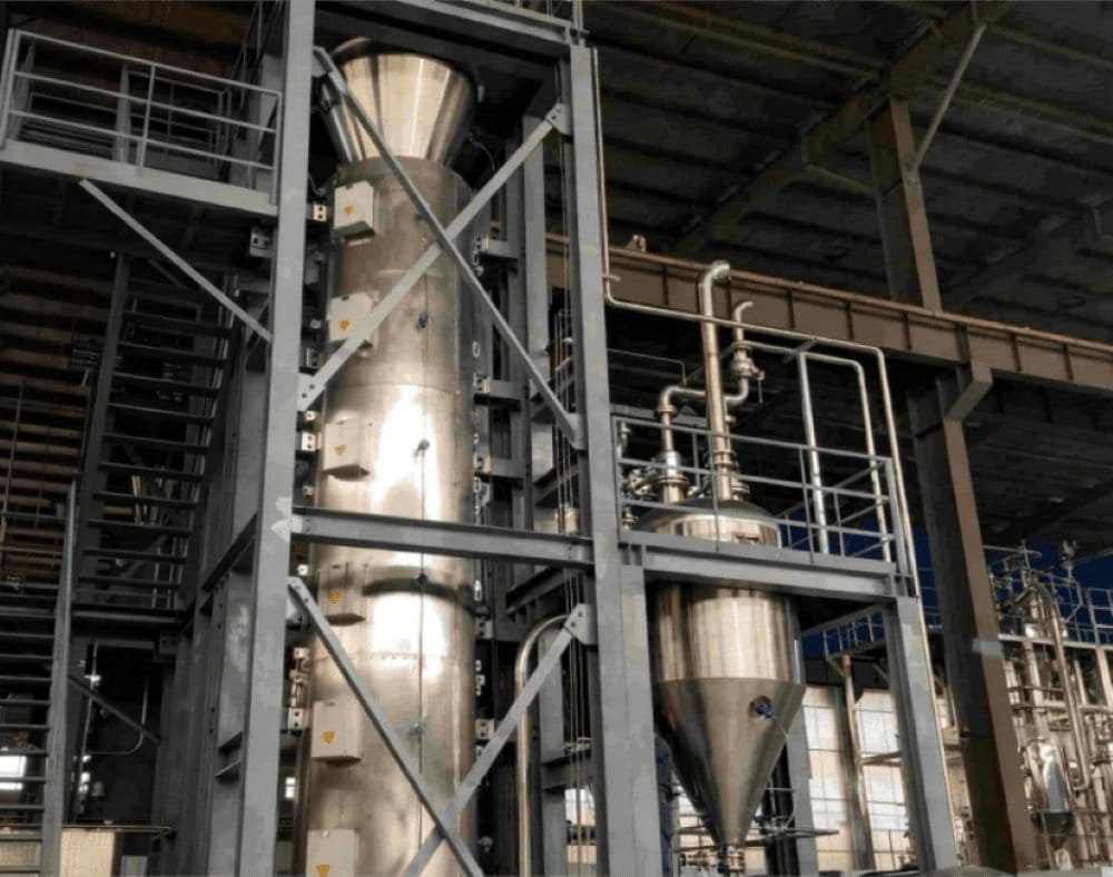
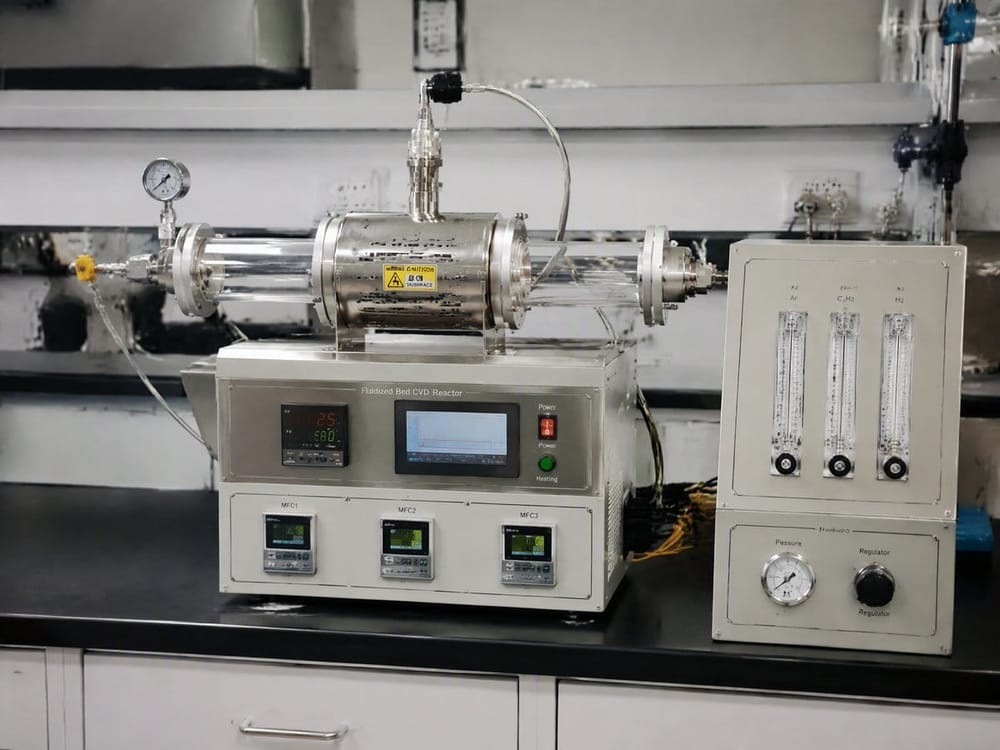
- Fluidized-bed deposition (core step): Gaseous silicon sources contact porous carbon particles thoroughly in the fluidized bed. Nano-silicon is deposited by pyrolysis at 450–650°C, embedding into the porous carbon pores to form silicon–carbon composite particles.
- Carbon coating: Methane, acetylene, or ethylene is used as carbon source for a secondary CVD step, depositing an amorphous carbon layer on the composite particle surface to buffer silicon volume expansion during lithiation and improve initial coulombic efficiency and cycle life.
- Cooling and passivation: The product is cooled and surface-passivated to reduce residual active groups, improving safety and storage stability.
- Screening and de-magnetization: Screened to required particle size, then de-magnetized and vacuum-packed for storage.
Step 3, fluidized-bed deposition, directly determines silicon content, distribution uniformity, and batch consistency. It is the highest-technical-content and largest-capital-investment step of the entire process.
II. FBCVD Reactor Selection: Eight Key Evaluation Points
Commercial FBCVD equipment differences are mainly in bed type, heating method, and sealing design. We recommend checking the following parameters item by item:
- Bed type and fluidization quality: Evaluate distributor plate open-area ratio, pressure-drop curve, and minimum fluidization velocity to ensure uniform particle fluidization without channeling or dead zones—this is the prerequisite for silicon distribution consistency.
- Temperature zone control accuracy: Silane pyrolysis is temperature-sensitive. The reaction zone axial temperature difference should be ≤±10°C, with support for rapid heating/cooling programs.
- Silicon source utilization: Examine residual silane rate in off-gas and silicon powder capture/recovery design. Silicon source cost accounts for a high proportion of material cost; utilization directly determines cost per ton.
- Anti-blocking and cleaning design: Silane pyrolysis easily produces nano-silicon powder that adheres to walls. Evaluate inner-wall polishing, purge gas lines, and online cleaning solutions to avoid frequent shutdowns.
- Sealing and safety: Silane is flammable and explosive. The equipment must have nitrogen purging, dual-stage sealing, leak detection, and explosion-proof interlocks, with supporting emergency response procedures.
- Scale-up experience: Prioritize suppliers with demonstrated scale-up performance from hundred-kilogram to ton-level. Channeling and flow maldistribution during fluidized-bed scale-up can only be avoided through engineering experience.
- Automation and data logging: Support full-process PLC control and temperature/pressure/flow curve recording to meet batch traceability requirements.
- Off-gas treatment: Silane off-gas must be combusted or water-washed before discharge. Evaluate supporting investments in off-gas incinerators and scrubbers.
III. Common Misconceptions
- Misconception 1: The larger the fluidized bed, the better. In practice, fluidization uniformity deteriorates significantly as bed diameter increases at ton-scale. Scale-up should be gradual after quality targets are met; avoid jumping orders of magnitude in one step.
- Misconception 2: Higher silicon content means higher capacity. Excessive silicon content amplifies volume expansion, accelerating cycle decay. Silicon content must be balanced against target specific capacity and cycle life (typically optimized within 5%–15%).
- Misconception 3: Good equipment alone is enough. CVD silicon–carbon yield also depends on the pore structure of the raw carbon, batch stability, and process window matching. Equipment selection must proceed in parallel with raw material validation.
IV. Summary
The industrial competition for CVD silicon–carbon anodes is essentially a competition of "fluidized-bed engineering capability + process window control capability." When selecting an FBCVD reactor, look beyond individual equipment parameters to the supplier's scale-up track record, silicon source utilization, and safety design. We recommend pilot validation with real raw materials before procurement, using batch consistency and cost-per-ton data as decision criteria. For FBCVD selection evaluation tailored to specific production capacity targets, please contact Songrui Refractory for technical support on fluidized-bed equipment and refractory lining solutions.